
Minimizes routine maintenance costs


Overview
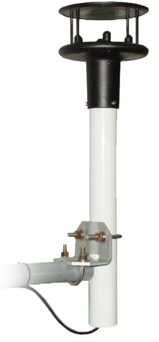
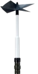
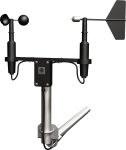
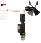
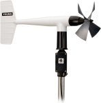
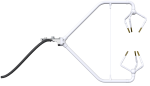
The WindSonic4 is a two-dimensional ultrasonic anemometer for measuring wind direction and speed. It provides an alternative to traditional mechanical cup and vane or propeller and vane anemometers. This sonic wind sensor outputs an SDI-12 signal that can be read a a compatible Campbell Scientific data logger. (See the Compatibility section.)
The WindSonic4 is not recommended for conditions where rime, ice, or horizontal snow will occur. This sensor is not heated. Please contact Campbell Scientific for information on a heated 2-D sonic anemometer that will work in these conditions.
Note: The mounting equipment supplied with this sensor may vary depending on which Campbell Scientific regional office the sensor is ordered from.
Read MoreBenefits and Features
- Low maintenance—no moving parts significantly reduces maintenance cost and time
- Provides a minimum detectable wind speed of 0.01 meters per second
- Compatible with most Campbell Scientific data loggers
Images


Technical Description
The WindSonic4 uses two pairs of orthogonally oriented transducers to sense the horizontal wind. The transducers bounce the ultrasonic signal from a hood, thus minimizing the effects of transducer shadowing and flow distortion.
Unlike mechanical anemometers, the WindSonic4 has no moving parts to be periodically replaced—minimizing routine maintenance costs.

. This activity is helpful when troubleshooting.")
Compatibility
Mounting
The WindSonic4 can be mounted with the 17387 mounting kit. This mounting kit is used to attach the sensor to a CM202, CM204, or CM206 crossarm. The crossarm is then mounted to a tripod or tower.
Data Logger Considerations
The WindSonic4 is connected to one control port, +12 Vdc, and ground. Up to ten WindSonic4s (each with a unique address) can be connected to one data logger control port.
Programming
The SDI12 instruction is used to collect data from the WindSonic4.
Specifications
| Applications |
|
| Sensor | 2-dimensional ultrasonic anemometer |
| Measurement Description | Wind speed and direction |
| Operating Humidity Range | < 5% to 100% RH |
| Operating Temperature Range | -35° to +70°C |
| Storage Temperature Range | -40° to +80°C (typical) |
| Input Voltage | 9 to 30 Vdc |
| Typical Current Drain | < 10 mA (@12 V) |
| Measurement Frequency | 40 Hz block averaged to a 1 Hz output frequency |
| Outputs Parameters | Polar (direction and speed) or orthogonal (Ux and Uy wind) |
| Output Signal | SDI-12 version 1.3 |
| Diameter | 14.2 cm (5.6 in.) |
| Length | 16.0 cm (6.3 in.) |
| Weight | 0.5 kg (1.1 lb) |
Maximum Cable Length |
|
| -NOTE- | For longer cable lengths, contact Campbell Scientific. |
| 1 Sensor Connected to 1 Port | 91.44 m (300 ft) |
| 2 to 10 Sensors Connected to 1 Port | 60.91 m (200 ft) |
Wind Direction |
|
| Range | 0º to 359° (no dead band) |
| Accuracy | ±3° |
| Resolution | 1° |
Wind Speed |
|
| Range | 0 to 60 m/s |
| Accuracy | ±2% (@ 12 m/s) |
| Resolution | 0.01 m/s |
Related Documents
Related FAQs
Number of FAQs related to WINDSONIC4-L: 8
Expand AllCollapse All
-
Yes, as long as these two conditions are met:
- There are no obstructions in the measurement volume.
- The temperature is between -35 to +70 degrees Celsius.
-
The fundamental measurement frequency of the WindSonic is 40 Hz (40 measurements per second). These measurements are then averaged to give an output at some slower output frequency. For a WindSonic programmed to produce 1 Hz data, all 40 measurements are averaged. (This is called a block average.) For a WindSonic that is programmed to produce 4 Hz data, each output is the block average of 10 fundamental measurements.
-
The WindSonic is not suitable for measuring the vertical wind component. The WindSonic measures the wind that passes through its measurement volume. It does not care what the orientation is. If the WindSonic is turned on its side, the reflecting top and body of the sensor will cause massive flow distortion of the wind vector, specifically for the horizontal component that is perpendicular to the reflective top. This flow distortion will most likely result in erroneous vertical wind measurements.
-
There are no user-serviceable parts on the WindSonic1 and WindSonic4. Should the WindSonic require service, it will start setting diagnostic flags. Campbell Scientific recommends that all datalogger programs record the total number of times the flags are set in an output period. For details, see the WindSonic Instruction Manual.
-
The fastest output frequency is 4 Hz for the WindSonic1 and 1 Hz for the WindSonic4.
-
All WindSonics (option 1 or option 4) are shipped from Campbell Scientific with an interface cable. If the cable has been lost, order a replacement. Order model WINDSONIC1CBL-Lxx for an option 1 or WINDSONIC4CBL-Lxx for an option 4, where xx is the cable length. The maximum cable length is 50 feet for option 1. The maximum cable on the SDI-1 bus is 200 feet.
-
Most Campbell Scientific sensors are available as an –L, which indicates a user-specified cable length. If a sensor is listed as an –LX model (where “X” is some other character), that sensor’s cable has a user-specified length, but it terminates with a specific connector for a unique system:
- An –LC model has a user-specified cable length for connection to an ET107, CS110, or retired Metdata1.
- An –LQ model has a user-specified cable length for connection to a RAWS-P weather station.
If a sensor does not have an –L or other –LX designation after the main model number, the sensor has a set cable length. The cable length is listed at the end of the Description field on the product’s Ordering tab. For example, the 034B-ET model has a description of “Met One Wind Set for ET Station, 67 inch Cable.” Products with a set cable length terminate, as a default, with pigtails.
If a cable terminates with a special connector for a unique system, the end of the model number designates which system. For example, the 034B-ET model designates the sensor as a 034B for an ET107 system.
- –ET models terminate with the connector for an ET107 weather station.
- –ETM models terminate with the connector for an ET107 weather station, but they also include a special system mounting, which is often convenient when purchasing a replacement part.
- –QD models terminate with the connector for a RAWS-F Quick Deployment Station.
- –PW models terminate with the connector for a PWENC or pre-wired system.
-
Many Campbell Scientific sensors are available with different cable termination options. These options include the following:
- The –PT (–PT w/Tinned Wires) option is the default option and does not display on the product line as the other options do. The cable terminates in pigtails that connect directly to a datalogger.
- In the –C (–C w/ET/CS110 Connector) option, the cable terminates in a connector that attaches to a CS110 Electric Field Meter or an ET-series weather station.
- In the –CWS (–CWS w/CWS900 Connector) option, the cable terminates in a connector that attaches to a CWS900-series interface. Connection to a CWS900-series interface allows the sensor to be used in a wireless sensor network.
- In the –PW (–PW w/Pre-Wire Connector) option, the cable terminates in a connector that attaches to a prewired enclosure.
- In the –RQ (–RQ w/RAWS Connector) option, the cable terminates in a connector that attaches to a RAWS-P Permanent Remote Automated Weather Station.
Note: The availability of cable termination options varies by sensor. For example, sensors may have none, two, or several options to choose from. If a desired option is not listed for a specific sensor, contact an application engineer at Campbell Scientific for assistance.
Case Studies
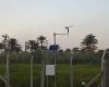
Overview Iraq’s Ministry of Agriculture has deployed a nationwide network of solar-powered, satellite-linked agrometeorological stations. The......read more
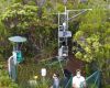
Tropical volcanic islands are biodiversity hotspots where the Critical Zone (CZ) remains poorly studied. In......read more
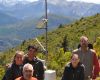
Introduction The Andes Mountains of Argentina are home to a rich and diverse group of organic......read more
Réunion is home to the only French tropical island ecocity located overseas. The purpose of......read more