Designed for long-term monitoring


Overview
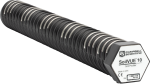
The CS616 measures the volumetric water content from 0% to saturation. The probe outputs a megahertz oscillation frequency, which is scaled down and easily read by a Campbell Scientific datalogger.
Read MoreBenefits and Features
- Compatible with most Campbell Scientific data loggers
- High accuracy and high precision
- Fast response time
- Designed for long-term unattended water content monitoring
- Compatible with AM16/32-series multiplexers, allowing measurement of multiple sensors
- Probe rods can be inserted from the surface or buried at any orientation to the surface.
Images

Technical Description
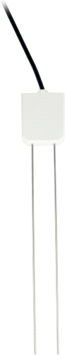
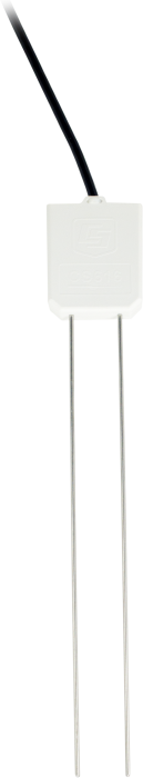
The CS616 is comprised of two 30-cm-long stainless steel rods connected to the measurement electronics. The circuit board is encapsulated in epoxy, and a shielded four-conductor cable is connected to the circuit board to supply power, enable probe, and monitor the output.
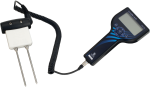
The CS616 measures the volumetric water content of porous media (such as soil) using the time-domain measurement method; a reflectometer (cable tester) such as the TDR100 is not required. This method consists of the CS616 generating an electromagnetic pulse. The elapsed travel time and pulse reflection are then measured and used to calculate soil volumetric water content.
Response Characteristics
The signal propagating along the parallel rods of the CS616 is attenuated by free ions in the soil solution and conductive constituents of the soil mineral fraction. In most applications, the attenuation is not enough to affect the CS616 response to changing water content, and the response is well described by the standard calibration. However, in soil with relatively high soil electrical conductivity levels, compacted soils, or soils with high clay content, the calibration should be adjusted for the specific medium. Guidance for making these adjustments is provided in the operating manual.


Compatibility
Please note: The following shows notable compatibility information. It is not a comprehensive list of all compatible products.
Dataloggers
| Product | Compatible | Note |
|---|---|---|
| CR1000 (retired) | ||
| CR1000X (retired) | ||
| CR1000Xe | ||
| CR300 (retired) | ||
| CR3000 (retired) | ||
| CR310 | ||
| CR350 | ||
| CR6 | ||
| CR800 (retired) | ||
| CR850 (retired) |
Additional Compatibility Information
RF Considerations
The RF emissions are below FCC and EU limits as specified in EN61326 if the CS616 is enabled less than 0.6 ms, and measurements are made less frequently than once a second. External RF sources can also affect the CS616 operation. Consequently, the CS616 should be located away from significant sources of RF such as ac power lines and motors.
Installation Tool
The CS650G makes inserting soil-water sensors easier in dense or rocky soils. This tool can be hammered into the soil with force that might damage the sensor if the CS650G was not used. It makes pilot holes into which the rods of the sensors can then be inserted. It replaces both the 14383 and 14384.
Data Logger Considerations
The reflectometer connects directly to one of the data logger’s single-ended analog inputs. A data logger control port is typically used to enable the CS616 for the amount of time required to make the measurement. Data logger instructions convert the probe square-wave output to period which is converted to volumetric water content using a calibration.
Specifications
| Measurements Made | Volumetric water content (VWC) of porous media (such as soil) |
| Measurement Range | 0% to saturation |
| Water Content Accuracy | ±2.5% VWC (using standard calibration with bulk EC of ≤ 0.5 dS m-1, bulk density of ≤ 1.55 g cm-3, and measurement range of 0% to 50% VWC) |
| Required Equipment | Measurement system |
| Soil Suitability | Long rods and lower frequency are well-suited for soft soil with low electrical conductivity (< 2 dS/m). |
| Rods | Not replaceable |
| Sensors | Not interchangeable |
| Operating Temperature Range | 0° to +70°C |
| Probe-to-Probe Variability | ±0.5% VWC in dry soil, ±1.5% VWC in typical saturated soil |
| Precision | Better than 0.1% VWC |
| Resolution | 0.1% VWC |
| Output | ±0.7 V square wave (with frequency dependent on water content) |
| Current Drain |
|
| Power Supply Voltage | 5 Vdc minimum; 18 Vdc maximum |
| Enable Voltage | 4 Vdc minimum; 18 Vdc maximum |
| Electromagnetic | CE compliant (Meets EN61326 requirements for protection against electrostatic discharge.) |
| Rod Spacing | 32 mm (1.3 in.) |
| Rod Diameter | 3.2 mm (0.13 in.) |
| Rod Length | 300 mm (11.8 in.) |
| Probe Head Dimensions | 85 x 63 x 18 mm (3.3 x 2.5 x 0.7 in.) |
| Cable Weight | 35 g per m (0.38 oz per ft) |
| Weight | 280 g (9.9 oz) without cable |
Related Documents
Related FAQs
Number of FAQs related to CS616-L: 10
Expand AllCollapse All
-
The CS616-L has a faster period output than the CS615, so it will not work with the 21X dataloggers.
-
Fine roots do not significantly affect the CS616-L/CS625-L reading.
-
Running the cable through electrical conduit or PVC pipe will protect the cable from rodents. A trench 30 to 60 cm deep will protect it from most other human or animal activity. Some customers have found that extra cable can be coiled and left inside a box, such as an irrigation valve box or something similar. When using a box, seal any holes that are large enough for rodents to enter. When cables are exposed on the ground surface, some customers have found that wrapping the cables in the metal screening used for screen doors discourages animals from chewing on them.
-
If the soil is very rocky, very dry, or very hard, Campbell Scientific recommends using a CS650G to make pilot holes before installing the sensor into the soil. When the soil is free of rocks, moderate to very wet, and relatively soft, it is usually possible to install the sensor rods and keep them parallel using gentle and steady pressure on the sensor head.
Note: Never strike the sensor head with a hammer or step on the sensor head to force the rods into the soil.
-
The cable for the sensors is rugged and resistant to damage from the sun and typical weather conditions. However, it is susceptible to damage from rodents, machinery, shovels, and so forth. Running the cable through electrical conduit or PVC pipe will help protect it, but this is not an absolute requirement. In areas where rodent activity is low, direct burial in a trench is usually sufficient. A particularly vulnerable location is where the buried cables exit the ground and enter the enclosure housing the datalogger. At that exit point, take steps to protect the cable from damage.
-
Campbell Scientific does not recommend splicing sensor cables. Sensors may be ordered with custom cable lengths, and Campbell Scientific recommends purchasing the correct length for the application. If the sensor cable needs to be lengthened, a junction box (if practical) is a more favorable option than a splice.
Note: A splice will void the sensor warranty, but a junction box does not modify the sensor and therefore does not void the warranty.
-
Most Campbell Scientific sensors are available as an –L, which indicates a user-specified cable length. If a sensor is listed as an –LX model (where “X” is some other character), that sensor’s cable has a user-specified length, but it terminates with a specific connector for a unique system:
- An –LC model has a user-specified cable length for connection to an ET107, CS110, or retired Metdata1.
- An –LQ model has a user-specified cable length for connection to a RAWS-P weather station.
If a sensor does not have an –L or other –LX designation after the main model number, the sensor has a set cable length. The cable length is listed at the end of the Description field on the product’s Ordering tab. For example, the 034B-ET model has a description of “Met One Wind Set for ET Station, 67 inch Cable.” Products with a set cable length terminate, as a default, with pigtails.
If a cable terminates with a special connector for a unique system, the end of the model number designates which system. For example, the 034B-ET model designates the sensor as a 034B for an ET107 system.
- –ET models terminate with the connector for an ET107 weather station.
- –ETM models terminate with the connector for an ET107 weather station, but they also include a special system mounting, which is often convenient when purchasing a replacement part.
- –QD models terminate with the connector for a RAWS-F Quick Deployment Station.
- –PW models terminate with the connector for a PWENC or pre-wired system.
-
Many Campbell Scientific sensors are available with different cable termination options. These options include the following:
- The –PT (–PT w/Tinned Wires) option is the default option and does not display on the product line as the other options do. The cable terminates in pigtails that connect directly to a datalogger.
- In the –C (–C w/ET/CS110 Connector) option, the cable terminates in a connector that attaches to a CS110 Electric Field Meter or an ET-series weather station.
- In the –CWS (–CWS w/CWS900 Connector) option, the cable terminates in a connector that attaches to a CWS900-series interface. Connection to a CWS900-series interface allows the sensor to be used in a wireless sensor network.
- In the –PW (–PW w/Pre-Wire Connector) option, the cable terminates in a connector that attaches to a prewired enclosure.
- In the –RQ (–RQ w/RAWS Connector) option, the cable terminates in a connector that attaches to a RAWS-P Permanent Remote Automated Weather Station.
Note: The availability of cable termination options varies by sensor. For example, sensors may have none, two, or several options to choose from. If a desired option is not listed for a specific sensor, contact an application engineer at Campbell Scientific for assistance.
-
The CS650-L and CS655-L are multiparameter smart sensors that send data by RS-232 serial or SDI-12 communications. The CS650-L and CS655-L measure temperature, period average, and signal attenuation (voltage ratio). The sensors calculate volumetric water content, permittivity, and bulk electrical conductivity. Permittivity and volumetric water content values are corrected for signal loss in conductive soil. Each CS650-L or CS655-L may be given a unique SDI-12 address so that many sensors can communicate with a datalogger while they are connected to the same communications channel. SDI-12 commands are used to poll the sensor. Both the CS650-L and the CS655-L are more expensive than the CS616-L.
The CS616-L output is a square sine wave whose frequency varies with changing bulk dielectric permittivity. It requires a datalogger capable of detecting the frequency or average period at which the sine wave crosses the zero volt threshold. Each CS616-L requires its own analog input channel on the datalogger. An enable voltage must be sent to the CS616-L to supply power and make a measurement. The period average reading is converted to volumetric water content with a quadratic or power function. The CS616-L makes no temperature or electrical conductivity measurement and does not compensate for signal loss in conductive soil. The CS616-L is less expensive than both the CS650-L and the CS655-L, but it does less.
-
- The CS616-L meets European noise emission standards, which are stricter than U.S. standards.
- The CS616-L period output is more linear than the CS615-L output.
- The CS616-L operates over a wider range of soil types than the CS615-L.
Case Studies
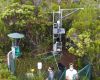
Tropical volcanic islands are biodiversity hotspots where the Critical Zone (CZ) remains poorly studied. In......read more
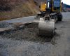
Korea Expressway Corporation (KEC) was established in 1969 to construct and manage expressways throughout South......read more
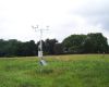
The Delaware Environmental Observing System (DEOS) is a real-time system dedicated to monitoring environmental conditions......read more
The West Texas Mesonet (WTM) project was initiated by Texas Tech University in 1999 to......read more