


Overview
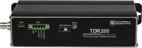
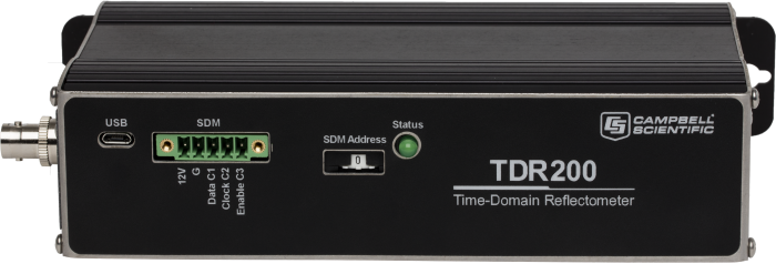
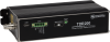
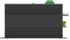
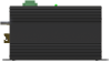
The TDR200 Time-Domain Reflectometer is the core of the Campbell Scientific time-domain reflectometry (TDR) system. TDR systems accurately determine soil volumetric water content, soil bulk electrical conductivity, rock mass deformation, or a user-specific time-domain measurement. One Campbell Scientific data logger can control multiple TDR200 reflectometers.
Read MoreBenefits and Features
- Low power (half the power of the TDR100)
- Robust
- High sensitivity
- High resolution
- Low noise
- Advanced waveform filtering
- Advanced waveform analysis algorithm
- Backward compatible with TDR100 systems (CRBasic data loggers only)
- 60 Hz frequency rejection
Images


3D/CAD Files:
Related Products
Technical Description
The TDR200 generates a short rise time electromagnetic pulse that is applied to a coaxial system that includes a TDR probe for soil water measurements. Then the reflectometer samples and digitizes the resulting reflection waveform for analysis or storage.
The elapsed travel time and pulse reflection amplitude contain information used by the on-board processor to quickly and accurately determine soil volumetric water content, soil bulk electrical conductivity, rock mass deformation, or a user-specific time-domain measurement.
The data logger collects a 250-point waveform and analyzes it in approximately two seconds. Each waveform can have up to 10,112 data points for monitoring long cable lengths used in rock mass deformation or slope stability. Advanced noise filtering and averaging make accurate measurements possible in noisy environments.
A Complete System
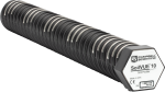
A complete TDR200-based system includes the TDR200, SDM8X50 multiplexers, data logger, power supply, enclosures, and probes. PC-TDR version 3 software supports TDR200 and sensor setup, troubleshooting, and program generation. This software is available, at no charge, from our website.
The SDM8X50 Multiplexer brochure, TDR Probes component category brochure, and Time-Domain Reflectometry System brochure provide additional information about the TDR system components.


Specifications
| Measurements Made | Volumetric water content (VWC) of porous media (such as soil), soil electrical conductivity (EC), rock mass deformation |
| Pulse Generator Output | 250 mV into 50 Ω |
| Output Impedance | 50 Ω ±1% |
| Time Response of Combined Pulse Generator & Sampling Circuit | ≤ 85 ps |
| Pulse Generator Aberrations |
|
| Pulse Length | 25.5 μs |
| Waveform Averaging | 1 to 128 |
| Operating Temperature Range | -40° to +85°C |
| Power Supply |
Unregulated 12 Vdc
(9.6 to 16 Vdc) 150 mA maximum, USB powered (5 Vdc) |
| Required Equipment | Measurement system |
| Dimensions | 21.6 x 5.1 x 10.7 cm (8.5 x 2.0 x 4.2 in.) |
| Weight | 0.79 kg (1.75 lb) |
Waveform Sampling |
|
| -NOTE- |
20 to 10112 waveform values over chosen length Distance is Vp=1. Time is one-way travel. |
| Range |
|
| Resolution |
|
Electrostatic Discharge Protection |
|
| Air | ±8 kV @ 2 Ω |
| Contact | ±4 kV @ 2 Ω |
| Surge | ±2 kV @ 2 Ω |
Current Drain |
|
| During Measurement | 120 mA |
| Sleep Mode | 1 mA |
Related Documents
Product Brochures
Compliance
Miscellaneous
Downloads
PC-TDR v.3.0 (7.34 MB) 15-12-2016
Support software designed for the TDR200 and is also compatible with the retired TDR100 Time-Domain Reflectometer.
Related FAQs
Number of FAQs related to TDR200: 2
-
In applications where TDR probes are used to measure soil water content, the maximum distance from the TDR probe back to the TDR100 (even through one or more multiplexers) cannot exceed 15 m (50 ft) when using RG58 coaxial cable; the CS605-L, CS630-L, and CS640-L TDR probes have an RG58 cable. When using low-loss coaxial cable, the distance cannot exceed ≈25 m (80 ft); the CS610-L, CS635-L, and CS645-L TDR probes have a low-loss coaxial cable.
In slope stability and rock mass deformation applications, the maximum coaxial cable length should not exceed ≈1 mile (5,280 ft). The maximum combined length of all SDM cables in the system should not exceed ≈76 m (250 ft).
Case Studies
Recent loss of life from large landslides in the United States (such as those in......read more