Overview
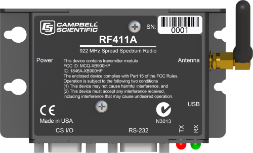
The RF411A is a 900 MHz radio designed for license-free use in several countries, including Australia and New Zealand. It provides a hassle-free way to create long-distance wireless links between your computer, data loggers, and measurement devices. The RF411A has a 920 to 928 MHz operating-frequency range and a configurable transmit-power output of 5 to 250 mW.
The RF411A is compatible with all of its RF400-series radio predecessors, including the RF410, RF411, and RF431. This also means that it is compatible with the CR210, CR211(X), and AVW211.
Note: The RF411A radios are recommended for existing installations that require compatibility with products such as the RF411, CR211, and AVW211. For new installations, Campbell Scientific recommends using the RF412 or RF451.
Read MoreBenefits and Features
- Rugged, low-cost transceivers
- Can be used in the field as a transceiver or in the office as the base station
- Transmits up to one mile with omnidirectional antenna; up to 10 miles with higher gain directional antennas at ideal conditions
- Settings stored in non-volatile memory
- RS-232 port for connecting to a computer; CS I/O port for connecting to a data logger
- Frequency-hops over 25 channels avoids interference from other spread spectrum radios
- Optional extended temperature testing
- Faster communication due to elimination of some small "link state packets"
- Ability to have stand-alone RF router/repeaters (up to 8 repeaters)
- Greater immunity to interference and RF collisions by using RF retries
- Reduced power consumption by the data logger, as the radios perform "packet address filtering"
- Built-in setup menus allow access to advanced functionality
- Designed for use in PakBus networks
Images


3D/CAD Files:
Related Products
Technical Description
The RF411A is a frequency hopping spread spectrum radio designed for 900 MHz license-free ISM band operation. It has a 920 to 928 MHz operating-frequency range and a configurable transmit power output of 5 to 250 mW. It provides one of three selectable active connections including CS I/O, RS-232, and USB. It has a reverse polarity SMA (RPSMA) antenna jack connection. It is over the air compatible with legacy 9XStream products including the RF410, RF411, RF431, CR210, CR211(X), and AVW211.

Compatibility
Communications
The RF411A is over the air compatible with the RF411, RF431, CR211, CR211X, and AVW211.
Other Spread Spectrum Radios
The RF411A is also compatible with the RF410 and CR210, but the communication protocol must be set to transparent. Also, if RF410 and RF411A radios will be in the same RF proximity, do not use 28, 44, 52, 56, or 60 for the RF410 Net Address. RF410 radios with Net Addresses of 28, 44, 52, and 56 interfere with RF411A radios with Net Addresses of 0, 1, 2, and 3, respectively. The RF410 Net Address of 60 interferes with all RF411A Net Addresses.
Campbell Scientific does not recommend using the RF411A in networks containing FGR-115 or RF450 radios.
Transparent and PakBus Protocols
Do not mix RF411A radios using the Transparent protocol setting with RF411A, RF411, RF431, CR211(X), or AVW211 devices using a PakBus protocol setting. This will produce unsuccessful RF traffic. However radios with the PakBus Aware and PakBus Node settings can coexist in the same network.
Data Logger Considerations
| Data Logger | RS-232 | CS I/O |
| CR200(X) |  |
|
| CR800/CR850 | |
|
| CR1000 | |
|
| CR3000 | |
|
| CR5000 | |
|
| CR9000(X) | |
|
| CR300 | * |
|
| CR6 | |
|
| CR510-PB | |
|
| CR10X-PB | |
|
| CR23X-PB | |
|
| Mixed-array data loggers | ** |
Notes:
*Use a 18663 null modem cable.
**It is possible to connect a mixed-array data logger (e.g., CR10, CR10X, CR23X, 21X, CR7) by using an SC932A or SC105 between the data logger's CS I/O port and the RF411A's RS-232 port.
Specifications
| Radio Type | Frequency Hopping Spread Spectrum (FHSS) |
| Frequency | 920 to 928 MHz |
| Country Used In | Australia, New Zealand |
| Transmission Distance |
|
| Power Output | 5 to 250 mW (software-selectable) |
| Receiver Sensitivity | -109 dBm (Campbell Scientific protocols will issue retries wherever a bit error occurs.) |
| Channel Capacity | 7 hop sequences share 25 frequencies. |
| RF Throughput Data Rate | 9.6 kbps |
| Data Rate | 10 kbps |
| Antenna Connector | Reverse Polarity SMA (RPSMA) jack |
| LEDs | Power on, Tx, Rx, diagnostics |
| RS-232 Baud Rate | 1200 to 115200 bps |
| CS I/O Modes | SDC 7, 8, 10, 11, and ME master |
| Average Current Drain |
|
| Power | 9 to 16 Vdc |
| Power Connector | 2.5 mm DC power jack |
| Operating Temperature Range |
|
| Communication Ports |
|
| Service Requirements | Shares frequency with other devices. Must not cause harmful interference to licensed radios. Requires line-of-sight. |
| Dimensions |
11.1 x 6.9 x 2.7 cm (4.4 x 2.7 x 1.1 in) Dimensions are from the tip of antenna connector to other side of case, and from the bottom of case to the top of DB9 connector jack screw. The width includes the thickness of the screw heads on the screws that hold the case together. |
| Weight |
|
Certifications |
|
| United States (FCC Part 15.247) | MCQ-XB900HP |
| Industry Canada (IC) | 1846A-XB900HP |
| C-TICK Australia | Yes, N3013 |
Related Documents
Product Brochures
Technical Papers
Related FAQs
Number of FAQs related to RF411A: 5
Expand AllCollapse All
-
If you have an RF401/RF401A/RF407/RF411A/RF412/RF427 network that has been working reliably for months and then suddenly fails with intermittent data collection, the site hasn’t changed, and there hasn’t been any new construction in the area, the issue may be caused by a piece of new equipment that was installed on the job site during the COVID-19 pandemic.
Because of the COVID-19 pandemic, some job sites implemented badge sensor technology for contact tracing and social distancing. Often, these devices operate on Wi-Fi or Bluetooth, but some of them operate in the 900 MHz range, which is used by our spread-spectrum radios and can, therefore, cause interference. Fortunately, you can resolve this issue using radio channel masking.
The following outlines the steps that were taken to correct this issue in one specific example:
- The datasheet for the COVID-19 badge equipment was found and reviewed to determine that it was operating from 915 to 926 MHz.
- The manual for the RF407 900 MHz Spread-Spectrum Radio was reviewed. The manual reported the frequency for bit 0 and bit 63 as 902.4 MHz and 927.6 MHz with a channel spacing of 400 KHz.
- Using a mathematical calculation, it was determined that masking channels 31 to 60 would block off 914.8 MHz up to 926.4 MHz.
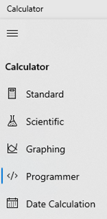
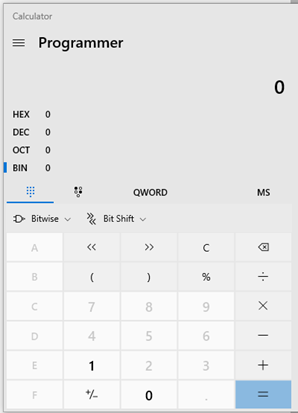
- Entering 0000000000000000000000000000001111111111111111111111111111110000 into a binary-to-hex converter provided a mask of FFFFFFFC0000000F. (The default Calculator app provided by Windows has a Programmer option listed under the hamburger menu that you can use for the conversion.)
- The mask of FFFFFFFC0000000F was used in the Radio Channel Mask setting, and the radio network returned to providing reliable operation.
For more detailed information about using radio channel masking, refer to your spread-spectrum radio manual. For example, the RF407-Series manual has a section devoted to this topic.
-
These radios ship with an SC12 serial cable and a 10873 RS-232 cable.
-
Antenna selection depends on multiple criteria:
- Consider how many stations a particular station needs to communicate with. For remote stations in communication with only one repeater or base station, a directional or Yagi antenna may be an appropriate choice. In contrast, repeater stations that receive data from many different locations will probably require an omnidirectional antenna.
- Consider if a high-gain antenna is needed to overcome the path between two points. Higher-gain antennas are larger and more expensive.
To help with antenna selection and site placement, consider renting and using a demo kit to test the pathway quality. Campbell Scientific offers a 900 MHz demo kit for the RF401, RF430, CR206X, and AVW206, as well as a demo kit for the RF450. Contact an application engineer at Campbell Scientific for assistance.
-
The RF401A and RF411A have distinct advantages over their predecessors, including greater maximum transmit power, lower average power consumption, improved packaging, and the inclusion of USB, RS-232, and CS I/O on a single device.
- The RF401A is compatible with all of its RF400-series radio predecessors, including the RF400, RF401, and RF430. The RF401A is also compatible with the CR205, CR206X, and AVW206.
- The RF411A is compatible with all of its RF400-series radio predecessors, including the RF410, RF411, and RF431. The RF411A is also compatible with the CR210, CR211X, and AVW211.