Overview
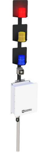
The RA110 allows an alarm system to be located several miles from the LW110 Lightning Warning System. The RA110 uses telemetry to receive electric-field information from the LW110. When the electric fields indicate that there is a potential for lightning, the RA110 triggers visual and audible alarms that warn of the possible dangers.
Read MoreBenefits and Features
- SAE Class II LED beacons with 100,000 hour rated lifetime
- 120 dB siren
- Allows the alarm system to be located several miles from the LW110 Lightning Warning System
- Controlled by a Campbell Scientific CR800 datalogger
- Includes two stainless-steel brackets for mounting to a flat surface
- Optional pole mount kit allows mounting to a pole with a 1.5- to 4-in. outside diameter
- Multiple RA110s can receive electric field information from one LW110 Lightning Warning System
Images

Technical Description
The RA110 consists of an RA100 Remote Strobe and Siren Alarm, a CR800 datalogger, a power supply, communication device, and an ENC14/16 enclosure. Communication options include fiber, spread spectrum radio, and Internet. There are also several options for mounting the enclosure and the RA100 alarm system.
Compatibility
The RA110 is used with the LW110 Lightning Warning System.
Specifications
| -NOTE- |
The RA110 has components that have their own specifications. To review these specifications, refer to the appropriate products below: |
Enclosure |
|
| Color | White (reflects solar radiation, reducing temperature gradients inside the enclosure without requiring a separate radiation shield) |
| Construction | Fiberglass-reinforced polyester enclosure with door gasket, external grounding lug, stainless-steel hinge, and lockable hasps |
| Enclosure Classification | NEMA 4X (before being modified for cable entry) |
| Internal Dimensions | 35.6 x 40.6 x 14 cm (14 x 16 x 5.5 in.) |
LED Beacons |
|
| Rated Lifetime | 100,000 hr |
| Colors | Red, amber, blue |
| Current Drain | 0.65 (peak), 0.26 (average) @12.8 Vdc |
| Diameter | 14 cm (5.5 in.) |
| Height | 16.3 cm (6.4 in.) |
Siren |
|
| Sound Output | 120 dBA |
| Operating Voltage | 4.8 to 14.4 Vdc |
| Current Drain | 620 mA (maximum) |
Related Documents
Product Brochures
Related FAQs
Number of FAQs related to RA110: 2
-
Most Campbell Scientific sensors are available as an –L, which indicates a user-specified cable length. If a sensor is listed as an –LX model (where “X” is some other character), that sensor’s cable has a user-specified length, but it terminates with a specific connector for a unique system:
- An –LC model has a user-specified cable length for connection to an ET107, CS110, or retired Metdata1.
- An –LQ model has a user-specified cable length for connection to a RAWS-P weather station.
If a sensor does not have an –L or other –LX designation after the main model number, the sensor has a set cable length. The cable length is listed at the end of the Description field on the product’s Ordering tab. For example, the 034B-ET model has a description of “Met One Wind Set for ET Station, 67 inch Cable.” Products with a set cable length terminate, as a default, with pigtails.
If a cable terminates with a special connector for a unique system, the end of the model number designates which system. For example, the 034B-ET model designates the sensor as a 034B for an ET107 system.
- –ET models terminate with the connector for an ET107 weather station.
- –ETM models terminate with the connector for an ET107 weather station, but they also include a special system mounting, which is often convenient when purchasing a replacement part.
- –QD models terminate with the connector for a RAWS-F Quick Deployment Station.
- –PW models terminate with the connector for a PWENC or pre-wired system.
-
Many Campbell Scientific sensors are available with different cable termination options. These options include the following:
- The –PT (–PT w/Tinned Wires) option is the default option and does not display on the product line as the other options do. The cable terminates in pigtails that connect directly to a datalogger.
- In the –C (–C w/ET/CS110 Connector) option, the cable terminates in a connector that attaches to a CS110 Electric Field Meter or an ET-series weather station.
- In the –CWS (–CWS w/CWS900 Connector) option, the cable terminates in a connector that attaches to a CWS900-series interface. Connection to a CWS900-series interface allows the sensor to be used in a wireless sensor network.
- In the –PW (–PW w/Pre-Wire Connector) option, the cable terminates in a connector that attaches to a prewired enclosure.
- In the –RQ (–RQ w/RAWS Connector) option, the cable terminates in a connector that attaches to a RAWS-P Permanent Remote Automated Weather Station.
Note: The availability of cable termination options varies by sensor. For example, sensors may have none, two, or several options to choose from. If a desired option is not listed for a specific sensor, contact an application engineer at Campbell Scientific for assistance.