This product is no longer available and has been replaced by: CS11-L. Some accessories, replacement parts, or services may still be available.
| Services Available | |
|---|---|
| Repair | No |
| Calibration | No |
| Free Support | No |
Overview
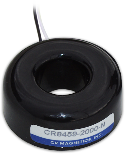
The CS15 is a modified version of the CS10 Current Transducer developed specifically for our CR200(X)-series dataloggers. It monitors ac current along an electrical wire for the range of 0.15 A to 125 A.
Read MoreBenefits and Features
- Ideal applications include motor or generator load conditions, efficiency studies, intermittent fault detection, and rough submetering
- No direct electrical connection to the electrical system
Images

Technical Description
The CS15 detects the ac current along an electrical wire using the magnetic field that is generated by that current. It is external to the wire jacket and has no direct electrical connection to the system. This transducer outputs a millivolt signal that our CR200(X)-series dataloggers can directly measure.
The CS15 can be used for motor or generator load condition monitoring, efficiency studies, intermittent fault detection, and rough submetering.
Compatibility
Data Logger Considerations
The CS15 was designed specifically for the CR200(X)-series dataloggers. It is measured with the VoltSE instruction. The measurement is generally taken repeatedly inside a measurement loop, then the RMS (root-mean-square) value is determined.
Specifications
- Measurement Range: 0.15 to 125 A
- Frequency: 50 and 60 Hz
- Insulation Resistance: 100 MΩ @ 500 Vdc
- High Potential: 2000 V
- Rated Current: 125 A
- Accuracy with 10 Ω Maximum Burden (resistive): typically ±5% of actual value with provided multiplier
- Operating Temperature Range: -25° to +55°C
- Case Material: Polypropylene resin
- Construction: Epoxy encapsulated
- Outer Diameter: 4.8 cm (1.89 in)
- Inner Diameter: 1.9 cm (0.75 in)
- Height: 1.7 cm (0.67 in)
Related Documents
Product Brochures
Related FAQs
Number of FAQs related to CS15-L: 4
Expand AllCollapse All
-
Yes, by connecting the red wire to ground rather than its normal location.
-
Not directly. If the CS15-L is connected to a CR200(X) datalogger, the datalogger can take the ac measurement and control a solid-state relay based on some threshold within the datalogger program. The solid-state relay can then control other relays, solenoids, or motor starters. (Use of a solid-state relay is preferred because the datalogger can trigger it with a small 5 Vdc mA signal.) For more information, see the “Measurement and Control Peripherals” section of the operator’s manual.
-
Most Campbell Scientific sensors are available as an –L, which indicates a user-specified cable length. If a sensor is listed as an –LX model (where “X” is some other character), that sensor’s cable has a user-specified length, but it terminates with a specific connector for a unique system:
- An –LC model has a user-specified cable length for connection to an ET107, CS110, or retired Metdata1.
- An –LQ model has a user-specified cable length for connection to a RAWS-P weather station.
If a sensor does not have an –L or other –LX designation after the main model number, the sensor has a set cable length. The cable length is listed at the end of the Description field on the product’s Ordering tab. For example, the 034B-ET model has a description of “Met One Wind Set for ET Station, 67 inch Cable.” Products with a set cable length terminate, as a default, with pigtails.
If a cable terminates with a special connector for a unique system, the end of the model number designates which system. For example, the 034B-ET model designates the sensor as a 034B for an ET107 system.
- –ET models terminate with the connector for an ET107 weather station.
- –ETM models terminate with the connector for an ET107 weather station, but they also include a special system mounting, which is often convenient when purchasing a replacement part.
- –QD models terminate with the connector for a RAWS-F Quick Deployment Station.
- –PW models terminate with the connector for a PWENC or pre-wired system.
-
Many Campbell Scientific sensors are available with different cable termination options. These options include the following:
- The –PT (–PT w/Tinned Wires) option is the default option and does not display on the product line as the other options do. The cable terminates in pigtails that connect directly to a datalogger.
- In the –C (–C w/ET/CS110 Connector) option, the cable terminates in a connector that attaches to a CS110 Electric Field Meter or an ET-series weather station.
- In the –CWS (–CWS w/CWS900 Connector) option, the cable terminates in a connector that attaches to a CWS900-series interface. Connection to a CWS900-series interface allows the sensor to be used in a wireless sensor network.
- In the –PW (–PW w/Pre-Wire Connector) option, the cable terminates in a connector that attaches to a prewired enclosure.
- In the –RQ (–RQ w/RAWS Connector) option, the cable terminates in a connector that attaches to a RAWS-P Permanent Remote Automated Weather Station.
Note: The availability of cable termination options varies by sensor. For example, sensors may have none, two, or several options to choose from. If a desired option is not listed for a specific sensor, contact an application engineer at Campbell Scientific for assistance.