This product is no longer available. Some accessories, replacement parts, or services may still be available.
| Services Available |
|---|
Overview
The 237 measures leaf wetness by determining the electrical resistance on the surface of the sensor (a wet surface is less resistant). It is primarily used to determine the percentage of time that a leaf surface is wet, versus the time it is dry.
Read MoreBenefits and Features
- Sensor is shipped unpainted so customer can choose appropriate surface finish that best fits their application
- Compatible with all Campbell Scientific data loggers (including the CR200(X) series)
- Imitates characteristics of a leaf
Images

Related Products
Technical Description
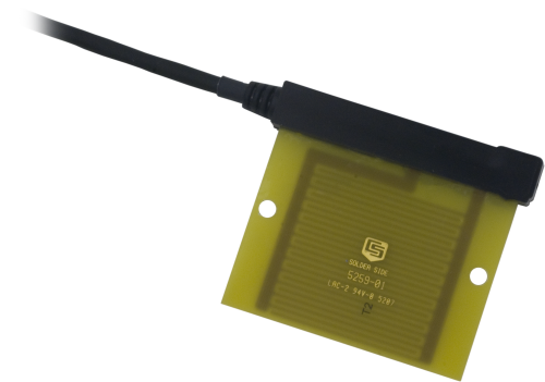
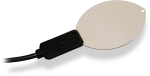
The 237 consists of a circuit board with interlacing gold-plated fingers. Condensation on the sensor lowers the resistance between the fingers, which is measured by the datalogger.
Droplets must touch two fingers simultaneously to change the sensor resistance. For this reason, the 237 is typically coated with flat latex paint, which spreads water droplets.
The color and type of paint affect sensor performance. Campbell Scientific supplies the sensor unpainted, allowing customers to determine the appropriate paint to apply to the sensor's surface. The appropriate pigmentation should closely emulate the properties of a typical leaf.
For more information on the effects of paint color and sensor angle on sensors of this type, see Gillespie, T.J., & Kidd, G.E., 1978. Sensing duration of leaf moisture resistance using electrical impedance grids. Canadian Journal of Plant Science 58: 179-187.
Calibration
The resistance of the sensor at the wet/dry transition point should be determined. A sharp change in resistance occurs in the wet-dry transition on the uncoated sensor; normally the transition is between 50 and 200 kohm. Coated sensors have a poorly defined transition, which normally occurs from 20 kohm to above 1,000 kohm. For best results, the leaf wetness sensor should be field calibrated because the transition point will vary for different areas and vegetation.
Compatibility
Please note: The following shows notable compatibility information. It is not a comprehensive list of all compatible products.
Dataloggers
| Product | Compatible | Note |
|---|---|---|
| CR1000 (retired) | ||
| CR1000X (retired) | ||
| CR300 (retired) | ||
| CR3000 (retired) | ||
| CR310 | ||
| CR350 | ||
| CR6 | ||
| CR800 (retired) | ||
| CR800 (retired) | ||
| CR800 (retired) | ||
| CR800 (retired) | ||
| CR850 (retired) | ||
| CR850 (retired) | ||
| CR850 (retired) | ||
| CR850 (retired) |
Additional Compatibility Information
Data Logger Considerations
The 237 requires one single-ended analog input and one switched excitation channel for measurement.
Specifications
| Resistance at Wet/Dry Transition |
|
| Operating Temperature Range | 0° to 100°C |
| Short-Term Survivability Temperature Range |
-40° to +150°C Sensor may crack when temperature drops below -40°C. |
| Painting | Sensor is shipped unpainted so customer can choose appropriate surface finish to best match the application. |
| Hole Spacing | 6.73 cm (2.65 in.) |
| Hole Diameter | 0.54 cm (0.213 in.) |
| Dimensions | 7.6 x 7.1 x 0.64 cm (3.0 x 2.75 x 0.25 in.) |
| Weight | 91 g (3 oz) with 3.05 m (10 ft) cable |
Related Documents
Product Brochures
Manuals
Related FAQs
Number of FAQs related to 237-L: 11
Expand AllCollapse All
-
Paint only with a flat latex paint. Usually, a high-quality, white, flat latex paint is used with a tiny amount of pigment.
-
The 237-L is not designed to be used as a conductivity sensor. To our knowledge, a few people have tried this but have been unsuccessful.
-
Variable, but always negligible. The theoretical maximum for each measurement is 5000 mV at 5 µA for less than 3 ms.
-
The mounting method used depends on the application. In plant canopies, consider mounting the 237-L so that it receives the least amount of solar radiation at noon. This means tipping the sensor, electrodes up, so that its sensing surface is parallel to the plane of the ecliptic. Tipping the sensor also minimizes the chance of water puddling on its surface.
On non-living surfaces, such as a man-made structure, consider mounting the 237-L flat against a flat surface on the shady side. This will cause the 237-L’s thermal characteristics to be more similar to those of the surface being studied.
-
Yes. The thermal characteristics of the 237-L are probably different from those of any surrounding objects, including leaves. Consequently, the 237-L will dry at a rate different from surrounding objects, including leaves.
-
No. The sensor signal can only be interpreted as either wet or dry.
-
Approximately 0.9 mm.
-
Only in the most basic sense. The signal output from the 237-L can only be interpreted as an indication of the presence of a conductive material bridging the two electrodes on its surface. If the circuit is open (infinite resistance or zero conductance), there is no conductive material. If the circuit is closed, there is conductive material.
The primary use of the 237-L is to indicate the presence of free water on the surface of surrounding objects. The thermal characteristics of the 237-L are probably different from those of any surrounding objects, including leaves. Consequently, the 237-L will dry at a rate different from surrounding objects, including leaves. Data from the 237-L are only interchangeable from measurement site to measurement site if the following are true:
- Each 237-L is prepared and maintained in the same way.
- Each 237-L is mounted in nearly identical environments.
Plant disease researchers found that if a 237-L sensor was placed in a plant canopy at a consistent position, with a consistent coating of a spreading material on its surface (that is, paint), they could estimate when free water was in the plant canopy. From this discovery, they were able to formulate disease emergence models. The resulting models tolerate significant deviation in moisture-presence data. Even so, use of a different spreading material, or difference in sensor positioning, may invalidate the data.
-
Most Campbell Scientific sensors are available as an –L, which indicates a user-specified cable length. If a sensor is listed as an –LX model (where “X” is some other character), that sensor’s cable has a user-specified length, but it terminates with a specific connector for a unique system:
- An –LC model has a user-specified cable length for connection to an ET107, CS110, or retired Metdata1.
- An –LQ model has a user-specified cable length for connection to a RAWS-P weather station.
If a sensor does not have an –L or other –LX designation after the main model number, the sensor has a set cable length. The cable length is listed at the end of the Description field on the product’s Ordering tab. For example, the 034B-ET model has a description of “Met One Wind Set for ET Station, 67 inch Cable.” Products with a set cable length terminate, as a default, with pigtails.
If a cable terminates with a special connector for a unique system, the end of the model number designates which system. For example, the 034B-ET model designates the sensor as a 034B for an ET107 system.
- –ET models terminate with the connector for an ET107 weather station.
- –ETM models terminate with the connector for an ET107 weather station, but they also include a special system mounting, which is often convenient when purchasing a replacement part.
- –QD models terminate with the connector for a RAWS-F Quick Deployment Station.
- –PW models terminate with the connector for a PWENC or pre-wired system.
-
Many Campbell Scientific sensors are available with different cable termination options. These options include the following:
- The –PT (–PT w/Tinned Wires) option is the default option and does not display on the product line as the other options do. The cable terminates in pigtails that connect directly to a datalogger.
- In the –C (–C w/ET/CS110 Connector) option, the cable terminates in a connector that attaches to a CS110 Electric Field Meter or an ET-series weather station.
- In the –CWS (–CWS w/CWS900 Connector) option, the cable terminates in a connector that attaches to a CWS900-series interface. Connection to a CWS900-series interface allows the sensor to be used in a wireless sensor network.
- In the –PW (–PW w/Pre-Wire Connector) option, the cable terminates in a connector that attaches to a prewired enclosure.
- In the –RQ (–RQ w/RAWS Connector) option, the cable terminates in a connector that attaches to a RAWS-P Permanent Remote Automated Weather Station.
Note: The availability of cable termination options varies by sensor. For example, sensors may have none, two, or several options to choose from. If a desired option is not listed for a specific sensor, contact an application engineer at Campbell Scientific for assistance.
Case Studies
The Delaware Environmental Observing System (DEOS) is a real-time system dedicated to monitoring environmental conditions......read more
The West Texas Mesonet (WTM) project was initiated by Texas Tech University in 1999 to......read more