
| Services Available | |
|---|---|
| Repair | No |
| Calibration | No |
| Free Support | Yes |
Overview
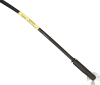
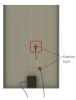
The 110PV is a thermistor that measures the temperature of a surface by direct contact. It typically monitors the temperature of a photovoltaic module, but can also monitor the temperature of other devices. This thermistor easily interfaces with our dataloggers, and is ideal for solar energy applications.
Read MoreBenefits and Features
- Compatible with all Campbell Scientific data loggers (including the CR200(X) series)
- Measures temperature across a wide range: -40° to +135°C
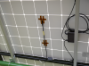
- Easy to install—adhesive strips on the 110PV’s smooth face adhere to the back of a solar panel or other device
- Aluminum disk protects thermistor and promotes heat transfer from surfaces
- Makes accurate measurements in environments with heavy electromagnetic interference
- Compatible with the CWS900-series interfaces, allowing it to be used in a wireless sensor network
Images

Technical Description
The 110PV consists of a thermistor encased in an aluminum disk. The disk protects the thermistor and promotes heat transfer from surfaces. An adhesive tab on the probe’s aluminum disk fastens the 110PV to the measurement surface. If the temperature may exceed 70°C, Kapton tape is also required to secure the probe; Kapton tape is offered as a Common Accessory (see Ordering Info).
The 110PV can provide the photovoltaic (PV) module temperature for solar energy applications. This measurement is useful since the output of a PV module is affected by its temperature. As the temperature of the PV module increases, its output decreases.
Compatibility
Please note: The following shows notable compatibility information. It is not a comprehensive list of all compatible products.
Dataloggers
| Product | Compatible | Note |
|---|---|---|
| 21X (retired) | ||
| CR10 (retired) | ||
| CR1000 (retired) | ||
| CR1000X (retired) | ||
| CR10X (retired) | ||
| CR200X (retired) | ||
| CR211X (retired) | ||
| CR216X (retired) | ||
| CR23X (retired) | ||
| CR300 (retired) | ||
| CR3000 (retired) | ||
| CR310 | ||
| CR500 (retired) | ||
| CR5000 (retired) | ||
| CR510 (retired) | ||
| CR6 | ||
| CR800 (retired) | ||
| CR800 (retired) | ||
| CR850 (retired) | ||
| CR850 (retired) | ||
| CR850 (retired) | ||
| CR850 (retired) | ||
| CR9000 (retired) | ||
| CR9000X (retired) |
Additional Compatibility Information
Mounting
For temperatures up to 70°C, an adhesive tab on the probe’s aluminum disk fastens the 110PV to the measurement surface. If the temperature may exceed 70°C, Kapton tape is recommended to secure the probe to the measurement surface. Kapton tape is available from Campbell Scientific (see Ordering Information).
The 110PV can be submerged to 50 ft, but the probe’s adhesive tab is not intended for submersion. Therefore the 110PV must be mounted to the measurement surface via a user-supplied method that is compatible with submersion.
Data Logger Considerations
Programming
The CR200(X)-series dataloggers use the ExDelSe instruction to measure the 110PV. The CR800, CR850, CR1000, CR3000, CR5000, and CR9000(X) can use either the BrHalf4W instruction or BrHalf instruction to measure the 110PV. For these data loggers, the BrHalf4W instruction is typically preferred because it reduces cable errors. The BrHalf instruction requires fewer input channels.
In Edlog, Instruction 5 is typically used to measure the 110PV. The ratio metric output is then converted to resistance and finally to temperature.
Specifications
| Sensor | Thermistor with specially designed protective aluminum disk |
| Measurement Description | Back-of-module temperature |
| Operating Temperature Range | -40° to +135°C |
| Temperature Survival Range | -50° to +140°C |
| Temperature Uncertainty |
|
| Sensitivity | +1°C |
| Steinhart-Hart Linearization Equation Error | 0.0024°C (at -40°C) maximum |
| Disk Material | Anodized aluminum |
| Cable Jacket Material | Santoprene |
| Cable/Probe Connection Material | Santoprene |
| Maximum Lead Length | 304.8 m (1000 ft) |
| Disk Diameter | 2.54 cm (1.0 in.) |
| Probe Length | 6.35 cm (2.5 in.) |
| Overmolded Joint Dimensions | 5.72 x 1.12 x 1.47 cm (2.25 x 0.44 x 0.58 in.) |
| Weight | 90.7 g with 3.2-m cable (0.2 lb with 10.5-ft cable) |
Related Documents
Product Brochures
Manuals
Related FAQs
Number of FAQs related to 110PV-L: 12
Expand AllCollapse All
-
Yes. After adhering the sensor to a dry surface, the sensor can be submerged up to 50 ft in depth.
-
There is no outside visual damage bending the cable over on itself 180°. But for long-term durability purposes, any bends should not be smaller than a 0.5 in. radius.
-
The sensor behaves exceptionally well (temperature uncertainty <0.2°C) between -40 and +80 degrees Celsius.
-
Some of the more common readings that indicate a sensor is malfunctioning include NANs (not a number) or unrealistic values such as a panel temperature reading of 500 degrees Celsius. If NANs occur, it is possible that there may be either programming or wiring errors. Double-check the setup, and contact Campbell Scientific for assistance if the issue continues. Depending on the sensor behavior, the sensor may need to be returned to Campbell Scientific for repair.
-
Currently, Short Cut only offers a half-bridge measurement option, and the resistance is not calculated. Each cable resistance is measured at the factory and labeled with its unique reading. That resistance value is called for when adding a 110PV-L sensor to the Short Cut program.
-
In either a 3-wire or 4-wire half-bridge configuration. For details, refer to the 110PV-L Instruction Manual.
-
That depends on which datalogger is being used and how the 110PV-L has been wired. For more details, see the 110PV-L Instruction Manual.
-
Yes, which means it can be wired directly to a datalogger.
-
It is possible that an older version of Short Cut is being used. Download the latest version of Short Cut.
If the latest version of Short Cut has already been downloaded, open the program.
- Go to Tools | Options and make sure that the Enable Creation of Custom Sensor Files box is checked.
- In the Generic Measurements folder, right-click the type of measurement to be made for the sensor, and select Create Custom Sensor.
- Set the fields according to the sensor’s specification, hide those fields that the user does not need to see after being set, and save the custom sensor file settings with the Save As button.
-
Note the difference between calibration and a field check. Calibration cannot be done in the field, as it requires an experienced technician and specialized equipment.
Field checks of measurements can be done to determine if the data make sense with the real-world conditions. Follow these steps to field check a sensor:
- Find a second sensor of the same type as the installed sensor whose data is in question. The second sensor will be used as a benchmark sensor and should be known to be accurate or recently calibrated.
- At the site, take readings using both sensors under the same conditions. The best practice is to measure both sensors side-by-side at the same time. Note that the sensors will never have the exact same measurement.
- Depending on the sensor model, if the difference in the readings of the installed and benchmark sensors is greater than the sum of the accuracies for both sensors, either return the installed sensor to Campbell Scientific for calibration or replace the appropriate chip.
- The 107-L/LC, 108-L/LC, 109-L, 110PV-L, and BlackGlobe-L temperature sensors can be calibrated.
- The HC2S3-L and HMP155A-L temperature and relative humidity sensors can be calibrated.
- The CS215-L has a replaceable chip for temperature and relative humidity. For more information, refer to the “Maintenance and Calibration” section of the CS215 instruction manual.
- The HMP60-L has a replaceable chip for relative humidity only. For more information, refer to the “Maintenance” section of the HMP60 instruction manual.